This blog post is going to be attempts at new methods of doing things as well as feedback for industry methods and best practice methods.
After speaking to my Lecturer Chris and George as well as getting feedback from Jack Kirkham I was suggested to start vertex painting on my floor. Although this was something I had already planned I tried something new, I tried to set up a parameter in substance designer allowing me to interchange the material how and where I want it. This method is good but comes at a massive cost in comparison to vertex painting.
After speaking to my Lecturer Chris and George as well as getting feedback from Jack Kirkham I was suggested to start vertex painting on my floor. Although this was something I had already planned I tried something new, I tried to set up a parameter in substance designer allowing me to interchange the material how and where I want it. This method is good but comes at a massive cost in comparison to vertex painting.
This minor mistake can cause memory issues later down the line if I was to do it this way but it was still fun to play with and to setup, I found out about this by using the parameter setup in substance designer and then googled if it can be put into UE4. The document found is linked in the references, although this method wasn't exactly what I had wanted it's still and option if I couldn't get the vertex painting to work. Not only did I find out about this method but I also found out about vertex blending, a way of bleeding two materials on top of each other, David Wilsons showcase below allows us to see what sort of idea/concept it relies on. Although this is mainly for organic materials it can still be used on my tiles, this is still a unnecessary method in comparison to vertex painting again it is still something used in industry as a way of painting organic materials together.
These methods although unnecessary work well in their own ways, for this project I'm going to keep it simplistic and go with my older more efficient method of vertex painting. It was nice to understand these processes and how they work but they aren't necessary as of yet in this project.

Aside from this there are a lot of methods based around UE4 and it's choosing which one is for you, I found this document on lighting which tells you from basic to industry levels of lighting. A link to this again is in the references. The reason I bring this up is because it allows me to further my knowledge on lighting and getting the correct lighting for the task at hand whether it be efficiency, portfolio piece or game ready. These different styles of lighting have so many options under it but choosing the correct one for your scenes or game is something that will be decided by the lead artist as it requires a good understanding and knowledge of what is needed. Understanding the lighting method is easy but putting them into practice is what makes it hard in terms of getting the correct lighting for your scene.
Another method that I was trying to do was to setup the parameters of a material from Substance Designer into UE4. Using the Substance addon for UE4 which allows you to setup the substance parameters using blueprints, I found out very soon after discovering how it's rarely ever used by talking with Chris (our lead tutor in asset creation and texture creation) because of the amount of memory and how expensive it normally is. I still attempted to give it a go but by doing this I found out just how expensive it was because UE4 crashed both times I attempted to test these methods. Either way I don't think I'll be attempting it again seeing as it was just wasting my time by crashing constantly and clearly it being so expensive. Here is the tutorial I was going to follow but ended up not (https://support.allegorithmic.com/documentation/integrations/blueprint-substance-parameters-151584792.html).
Another method that I was trying to do was to setup the parameters of a material from Substance Designer into UE4. Using the Substance addon for UE4 which allows you to setup the substance parameters using blueprints, I found out very soon after discovering how it's rarely ever used by talking with Chris (our lead tutor in asset creation and texture creation) because of the amount of memory and how expensive it normally is. I still attempted to give it a go but by doing this I found out just how expensive it was because UE4 crashed both times I attempted to test these methods. Either way I don't think I'll be attempting it again seeing as it was just wasting my time by crashing constantly and clearly it being so expensive. Here is the tutorial I was going to follow but ended up not (https://support.allegorithmic.com/documentation/integrations/blueprint-substance-parameters-151584792.html).

Looking further into industry methods and upcoming methods, I found a bunch of research and new-upcoming scripts that allow things like Maya to basically do what Zbrush does in terms of Zremesher. It's called polyRetopo & polyRemesh, these two small lines of code work in making a mesh increase the amount of geometry as well as bring down the tri-count the same that sub-divide and Zremesh work in Zbrush. The way this could work is replacing the whole retapology process as a whole, I've looked into the process and tried to get a understanding of how it works. The research I found out is that this doesn't yet work with imported assets from Zbrush that already contain a lot of geometry as it requires the polyRemesh part for it to work. Shown below are some pictures of it being done on a simple cube.

Step 1 create object.

Step 2 in the MEL script type polyRemesh; and it will come up with the settings on the right allowing you to change the density amount.

Steo 3 in the MEL script type polyRetopo; and it will give you the options on the right to let you change the amount you want to bring it down along with some other smaller settings allowing you to clean up the retopology. Although this is a new and upcoming addon that works but only with objects in Maya it's definitely something to look out for in the future. If you wish to delve into this further and get more of a understanding there is a freelance man making an addon to do the same concept for Maya and 3DSmax which is called QuadRemesher a link to the polycount thread will be in the references. This could potentially change the way we model but for now we can stick to quad draw as this is still in its 'beta' form and being tested. The original forum post I found for QuadRemesher (https://polycount.com/discussion/208030/quadremesher-new-auto-retopo-plugin-for-maya-3dsmax).
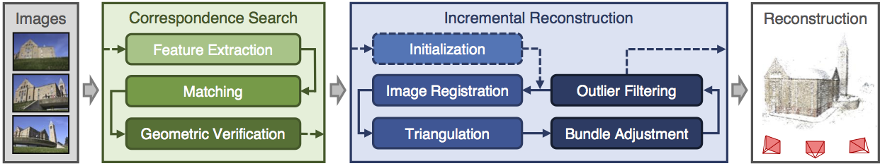
Another area I've been looking at is photogrammetry in terms of generating assets and substitute like assets which allows for a speedy realistic looking process. I personally tried touching on this, mistakenly trying the hardest thing known to photogrammetry (fur) without realizing but the results came out terribly but I'm glad I understand the process and how I can make these things game ready as well as the process needed. Below is my terrible attempt but an attempt none-the less. The programs I used to create the base was Colmap and from there created the dense reconstruction of the object meaning that the object and all the surroundings of the photos taken would print in 3D using points. This would normally create a really dense and high-poly 3D model that would need to be retapologised and not only this the process was long and tedious in terms of rendering and CONSTANT crashing unless you're using a high-end server to render. This was one way of looking into new methods that I personally wont be using again until computers are much more capable and stronger. Not only that I need to increase my knowledge in this area vastly before trying this again.

A good example of this overall process is shown below in the diagram. Firstly you start with the images, extract them out into the program, making sure they match each photo in the 'string' (string meaning line of photos taken) then trying to read the photos and turning it into a geometric form. Then from there as you have imported all the photos and made sure they have been read correctly by the software you would begin then a dense reconstruction creating a sparse map, once that render is complete you would then do the same process in terms of creating a dense depth map which is using the sparse map to be created and allowing the points to be shown in 3D forms. Then from there you would use the Fusion map to fuse it all together to make one and slowly build up your model. You would then normally by this point have some level of point to point 3D model without any textures or faces which then would be merged together after the Fusion has completed. After this you would then use the Stereo node which builds the textures onto the object for them to be exported into a games engine (Obj format) and allow you to retapologise over the top. You can then from here take the texture and apply it to your low-poly by baking it on (Normally done in blender but I'm working on finding out the way to do it in Maya). (A good tutorial document https://colmap.github.io/tutorial.html found also in references)
I then went and tried the same technique with a material, again it didn't come out as well as I wanted but that's because it was a single photo scanned and put into Substance B2M. The outcome is the image below. I basically used B2M to create this texture as most of it was necessary in getting a repeatable texture as well as creating the texture maps for this. It looks highly detailed but at the same time terrible in terms of looking realistic, a better man made job could be done in substance given the time but as for creating the material itself taking a photo and scanning it in would be ten times as fast in relation to creating a graph of this caliber. It all depends on the outcomes and how fast you are with substance designer. This is what the company Dice look for in people and most of their environment as they're looking for realistic results, if I was wanting a job for Dice I would follow these procedures.

This again isn't necessary unless of course you're looking for this result, in terms of understanding how it works I am still very minuscule in knowledge in comparison to most on this but attempts are attempts and learning the processes has easily shown further progression on my knowledge overall. This process helped me mostly understand the levels of memory and capabilities of computers and computing helping me understand why we make games as efficiently as we do.
Finding new documentation online is always fun and experimenting with it all helps me to learn more and more. Ilya Nedyals forum piece on lvl80 helps me understand how vertex color and texture color works, one is used as color ID and one is used as material ID. Vertex color uses a point cloud to color an object but texture uses UV co-ordinates. The idea behind this was to create a rubble pile with a ground plane that allows a material to be tiled over it. After struggling to understand the process completely I asked my Lecturer Chris for help but he also has never seen it done this way and the only other one who'd have a complete understanding of it Mark was away due to circumstances. Meaning I would have to fix this myself again and get more of a understanding of it by following the tutorial and understanding the complete process. Surprisingly this was the hardest to get an understanding of because of the process and the amount of small details, I imagine that once mastering this process the results can be endless. Normally you wouldn't use ZBrush for this method but after recently finding out you can set the poly groups to hold information and then using poly paint you can enable different colors to be painting souly onto different groups in ZBrush. You would then apply this to your UV map to create the texture and from there bake that onto the low-poly in something like Substance Painter using the .Obj file or any other that would carry texture/color information and bake it in allowing it to bake on the results you want.
(Trust, 2019)
Mesh decals were recommended to me as they would allow baked information to be presented on top of the object and add in small amounts of geometry changing the shape and look of the mesh. A normal decal is normally just paint or normal maps but this version allows you to change most of the geometry shown in the image below. Taken from the Unreal engine forum and how showcasing how it works. It would normally use tessellation to give off the effect further but it depends on what you prefer and on your budget of course.
(Docs.unrealengine.com, 2019)
Although vertex painting is a normal part of environment creation for me, I decided to try something new. I wanted to get baked data along with masking off an area for non-baked data to come in and allow the texture to work as a result. After asking lecturers, no one had a definitive answer they were only suggestions on how to go about it. My lecturer Stephen was the one to suggest what is now the outcome of this vertex paint. I wanted to test firstly the baked part to ensure this could work using just the UVs and exposing them on a separate UV channel from the tileable. As you can see from the textures below one is baked into the UV and one is tiled. I further decided to change the amount and the co-ords of the assets UVs to help the mask work correctly when baked in using UV 0 as the baked texture and UV 1 as the tiled texture. I then went ahead and made the mask, basked it in and went from there.

From this graph adn you can see it's cleverly split, the mask is multiplied by the tile-able allowing it to tile over the white areas and then from there it is lerped the same with the vertex paint as it would any other way using the same masks as Base Color, Normal and then RMA. This method seemed to have worked meaning my small masked area has a tiled texture showcasing a basic texture, the rest being baked in. This means now that I can add in the mesh decals learnt from before on top giving me a better looking result as well as having a break up in the textures showing off further detail. Although this is very expensive it's only for a portfolio piece so doing it in this instance is acceptable. I doubt very much it'll be acceptable in any other case, you would probably prefer to setup a master material in this instance instead if I was to do it again.

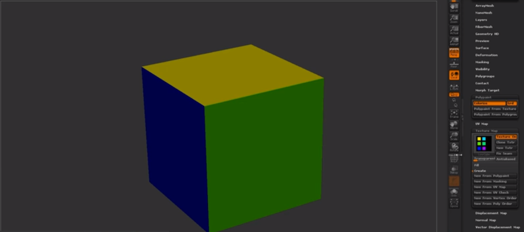
After exploring many ways of doing retapology and understanding why we do it and how we go about it I delved into the understanding of ZRemesher and how it works. I found out about PolyPaint which is a way of choosing a portion of a mesh and having things done to it through color. The way I went about using this is ZRemesher was understanding that red means to give higher amounts of polys whereas blue means to give off a lower level of poly meaning less definition or resolution in that one area in comparison. The way I went about using this to my advantage was using the photogrammetry piece which using vert colors for texture in here as ZBrush reads vert colors and not texture UVs. Here is my PolyPainted before and after.

Before with PolyPaint applied.

After with the final results showcasing the lower poly areas and the more dense.
References:
Docs.unrealengine.com. (2019). Using Mesh Decals. [online] Available at: https://docs.unrealengine.com/en-us/Engine/Rendering/Materials/HowTo/MeshDecals [Accessed 1 Apr. 2019].
L. Schoenberger, J. (2019). Tutorial — COLMAP 3.6 documentation. [online] Colmap.github.io. Available at: https://colmap.github.io/tutorial.html [Accessed 14 Feb. 2019].
Support.allegorithmic.com. (2019). Blueprint: Substance parameters - Substance Integrations. [online] Available at: https://support.allegorithmic.com/documentation/integrations/blueprint-substance-parameters-151584792.html [Accessed 14 Feb. 2019].
Trust, J. (2019). #AskZBrush: “How can I generate a Color ID map from Polygroups?”. [online] YouTube. Available at: https://www.youtube.com/watch?v=RYGkbSUaHHg [Accessed 1 Apr. 2019].
Wilson, D. (2019). Vertex Blending example. [online] Dave Wilson 3D Artist. Available at: http://ubudave.weebly.com/blog/vertex-blending-example [Accessed 10 Feb. 2019].
Wong, A. (2019). Dense Depth Map Reconstruction from Sparse Measurements Using a Multilayer Conditional Random Field Model. [online] Citeseerx.ist.psu.edu. Available at: http://citeseerx.ist.psu.edu/viewdoc/download?doi=10.1.1.715.8214&rep=rep1&type=pdf [Accessed 14 Feb. 2019].
https://polycount.com/discussion/208030/quadremesher-new-auto-retopo-plugin-for-maya-3dsmax
https://80.lv/articles/rubble-modular-set-production/
https://80.lv/articles/rubble-modular-set-production/
No comments:
Post a Comment